You can not select more than 25 topics
Topics must start with a letter or number, can include dashes ('-') and can be up to 35 characters long.
|
|
3 weeks ago | |
|---|---|---|
| images | 3 weeks ago | |
| kicad | 3 weeks ago | |
| .gitignore | 3 weeks ago | |
| README.md | 3 weeks ago | |
README.md
Low side MOSFET switch
- Fits a AO3400, 2301V or similar SOT23-3 N-MOS transistor
- Lets you control a 5A load from a 3.3V logic pin
- Designed at ELAB, bare PCBs and matching transistors can be found in the SMD drawers
Basic configuration
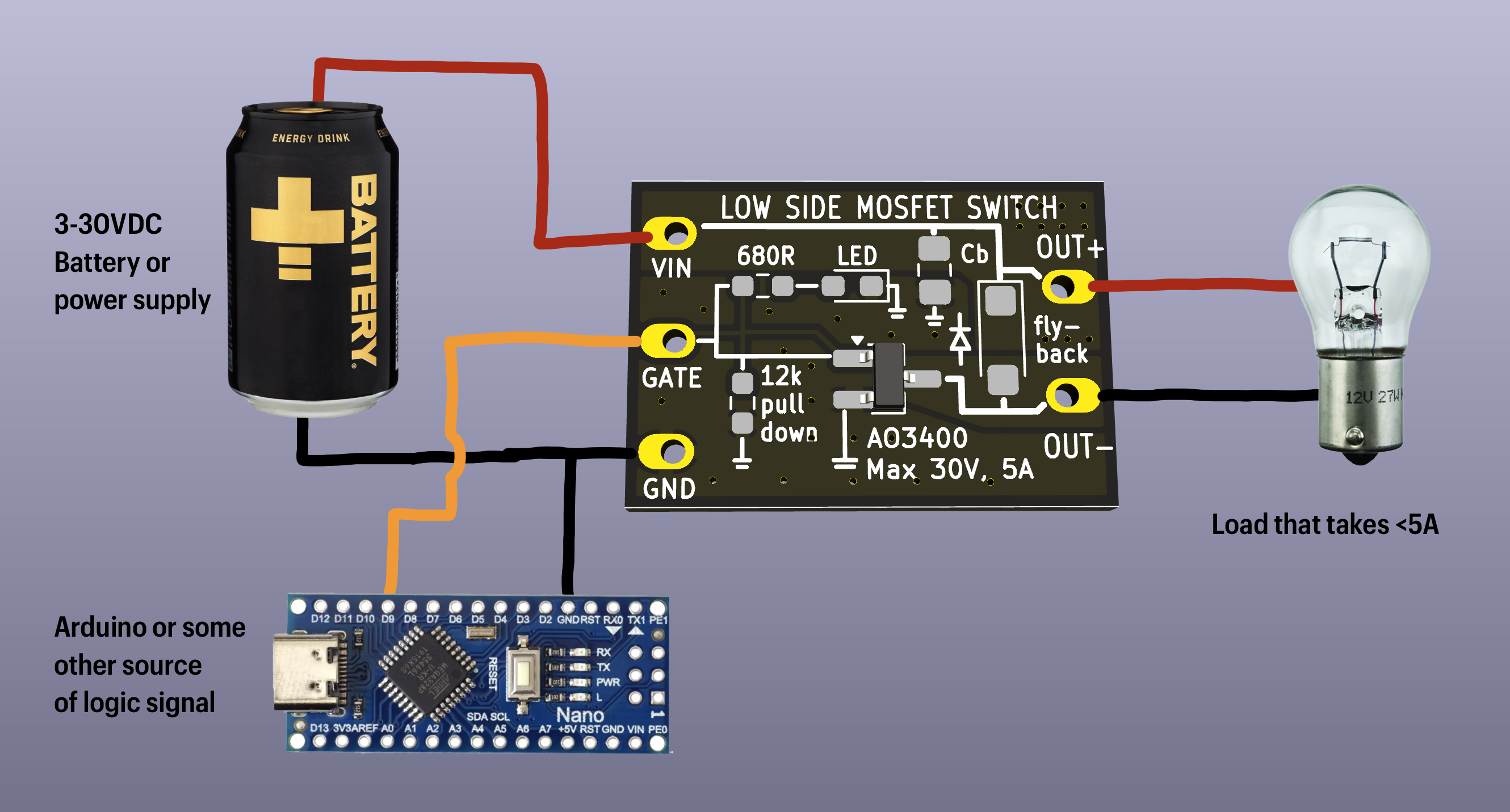
- Only the transistor needs to be populated, all other components are optional
- This configuration is suitable for RESISTIVE loads for example:
- LEDs with suitable resistors
- Heating elements
- Incandescent bulbs
- small inductive loads should ok OK like a tiny < 0.5A DC motor
Notes and tips
- This is a LOW side switch. OUT+ is always connected to VCC, only OUT- is switched. Because of this, this board is not recommended for switching modules that have more connections than just VCC and GND
- At 5A the transistor will get hot. Ventilation might be necessary
- Use wires thick enough for the current. AWG24 or better for 5A
- Remember that max 5A 30V does not mean it's ok to do 30A 5V! But you knew that, right?
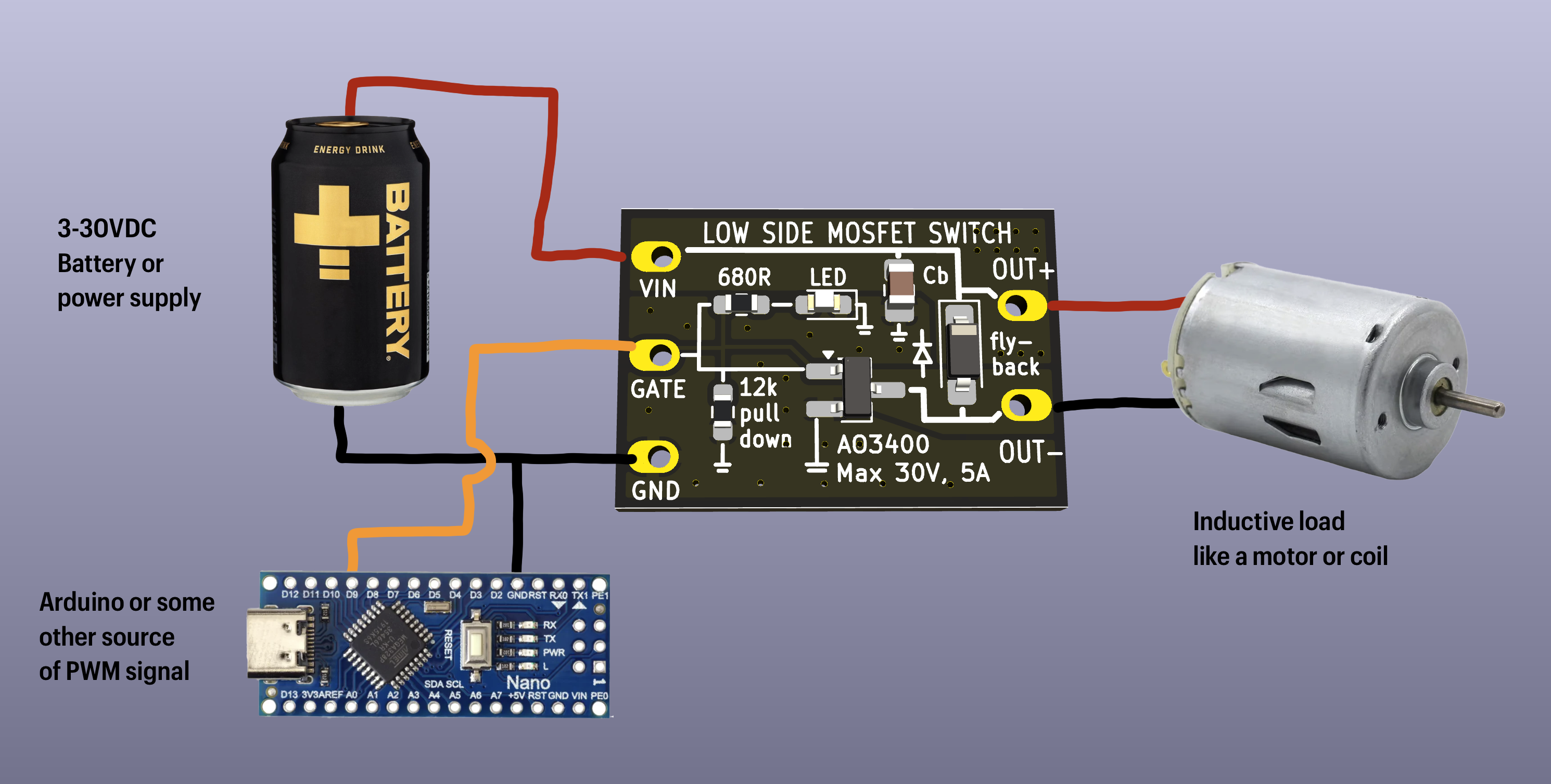
To use with inductive loads (DC motors, coils, speakers, etc)
- Populate the FLYBACK DIODE
- It protects the transistor from flyback voltage, caused by switching inductive loads
- Recommended diode: SS34 in SOD-123 package
- Note the direction of the diode - stripe towards VCC
Proportional "analog" control
- To control the power of the load (instead of just ON/OFF operation), use PWM
- The "analogWrite()" of an arduino produces a suitable PWM output
- Do not use a potentiometer at the gate! The FET will not enjoy that at all
Other optional components
Gate pull-down resistor
- Strongly recommended
- Ensures safe operation when a controlling MCU is booting / sleeping / disconnected
- Allows use with simple pushbutton as source of control signal
- Can be anything between 1k and 100k, in 0603 package
LED and its resistor
- LED shows status of control line - shines when switch is ON
- Recommended resistor: 330 - 2700Ohms, depending on MCU voltage and LED
- Both the resistor and LED are in 0603 package
Bypass capacitor
- Only useful when intending to PWM the load at higher frequencies (>10kHz)
- Reduces electromagnetic interference emitted by the input cables
- Might somewhat improve performance of switched device
- 1-100uF, must be rated for at least VIN * 1.5
- Footprint for 0603 package, but an 0805 might fit as well.
Other options
- For bi-directional motor control, use a motor driver or H-bridge, like this one
- For digital modules, like an ADC or OLED module, use a HIGH-SIDE switch. A high side switch module based on a CH217 is coming to elab "soon".
Made at ELAB by Marek Baczynski. Find him on the ELAB slack if you have any questions