You can not select more than 25 topics
Topics must start with a letter or number, can include dashes ('-') and can be up to 35 characters long.
|
|
8 months ago | |
|---|---|---|
| datasheets | 8 months ago | |
| images | 8 months ago | |
| kicad | 8 months ago | |
| .gitignore | 8 months ago | |
| README.md | 8 months ago | |
README.md
18V 5A H-Bridge breakout board
- For driving DC motors, coils or other inductive loads
- Bi-directional output control
- 3.0-18V input voltage
- 5A continuous output current, up to 9A pulse
- 1.8V to 6.0V input logic compatible
- PWM compatible, for output power level control
- Overcurrent protection
- Short circuit protection
- Overheat protection
- Integrated flyback diodes
- Pretty idiot-proof
- Uses CP2119L or TMI8260SP integrated circuit
Basic operation

- Logic HIGH on the FORWARD pin makes the motor spin FORWARD (M+ becomes VIN, M- becomes GND)
- Logic HIGH on the REVERSE pin makes the motor spin REVERSE (M+ becomes GND, M- becomes VIN)
- Logic HIGH on BOTH pins makes the motor ACTIVELY BREAK (M+ becomes GND, M- becomes GND)
- Logic LOW on BOTH pins makes the motor FREESPIN (M+ floats, M- floats)
"Analog" control
- The power of the motor can be precisely adjusted (0-100%) by applying a PWM SQUARE WAVE to the FORWARD/REVERSE pins
- Recommended PWM frequency: 100Hz - 5KHz
- Max frequency: 30KHz
- "analogWrite()" on Arduino produces a suitable 490Hz square wave with 256 levels of control
- The control PWM from the input is simply directly applied to the output, there is no magical logic in the device. The provided PWM frequency will be present on the motors.
- Higher frequencies cause switching losses and non-linear power scaling
- 1-2KHz will cause the most annoying coil whine sounds
- Low frequencies might cause noticable vibrations
- 400Hz is a good starting point
- You can not provide an analog input (like from a potentiometer) to the inputs of this device!
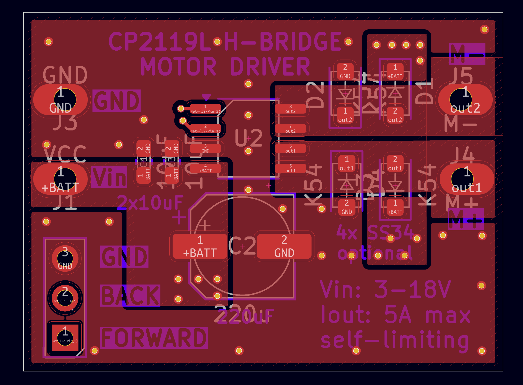
PCB assembly / component configurations
For Voltage 3-18V and Current 0-5A (basic configuration)

- Populate the TMI8260 (duh!). Note where pin 1 (marked) goes!
- Populate '2x10uF' with included ceramic capacitors
- Populate '220uF' with included polymer aluminium capacitor. Note where the negative goes!
- Skip the additional flyback diodes
- This works with PWM frequencies up to 5KHz
For PWM frequency > 5KHz
- If the expected current is low (<3A), you can probably just use the basic configuration
- Otherwise, add 4x flyback diodes on the PCB
- SS54 or SS34 diodes, in SOD-123L package
- They are difficult to solder, sorry!
For Voltage<10V AND Current<2A:
If you don't need the high power of this chip, consider using the DRV8835 module instead. It is cheaper and comes pre-assembled.
For ONE directional control:
If you don't need bi-directional control, consider just using a N-MOSFET and flyback diode instead. Cheaper, simpler.
Built in protections
The TMI8260/CP2119 has protection features that allow it to protect ITSELF
- It cannot protect the connected motor/coil - make sure VIN is a voltage that the motor can handle!
- It cannot fully protect the power source - make sure it can handle the current the motor will take!
Overcurrent / short-circuit protection
- If the connected motor / coil attempts to take more than > 9A, overcurrent protection kicks in
- The device will stop supplying power for approx 50 microseconds, and let the current drop
- After that, the device will automatically retry applying current
- This is very helpful when starting large motors from a standstill - the surge current will be effectively limited, and the motor will slowly spin up instead of taking infinity amperes.
- This does protect the power source by limiting the consumed current to approx 9A
- This feature relies on the inductance of the connected motor/coil. If the inductance is too low, the safety feature will not have time to react before the current becomes too high.
Overtemperature protection
- If the TMI8260 gets too hot (>150C) during continuous operation, it will temporarily stop providing power to the load
- After cooling down, it will automatically return to normal operation
Integrated flyback diodes
- Inductive loads tend to induct reverse voltages that may damage drive circuitry
- The TMI8260 has integrated flyback diodes (inside the chip) that can handle most use cases
- The PCB has space for additional external flyback diodes, for more extreme cases (see "Use cases")
Parts included in the kit:

- Breakout PCB
- TMI8260SP-MS chip
- Polymer aluminium capacitor (SHENGYANG SM227M025E0600 220uF 25V)
- 3x Ceramic capacitors (10uF 25V 0603)
Documentation

 TMI8260SP-MS datasheet (in Chinese)
Future improvements
Thermal management

- Most of the heat from the IC seems to be dissipating though the OUT1 / OUT2 pins
- Therefore, the OUT1 / OUT2 polygons should be enlarged, for better cooling
- Maybe the IC should be moved more towards the middle of the board
- Maybe the board could be made a little bigger, for better heat sinking
- Right now the board can just about handle 5A, but the chip gets very hot
Solderability
- The large cap is very difficult to solder
- Some thermal reliefs can make it much easier, while probably not impacting performance in any significant way
- The optional flyback diodes are difficult to solder
- The footprint should be made hand-solderable (by enlarging the pad by a lot)
Extra features
- Spots for adding LED indicators for FORWARD and REVERSE signal levels might be neat
- A screw hole or two, for easy monting. Maybe just a single M2
Made at ELAB by Marek Baczynski. Find him on the ELAB slack if you have any questions