You can not select more than 25 topics
Topics must start with a letter or number, can include dashes ('-') and can be up to 35 characters long.
4.7 KiB
4.7 KiB
18V 5A H-Bridge breakout board
- For driving DC motors, coils or other inductive loads
- Bi-directional output control
- Input 3.0-18V
- Output up to 5A continuous, up to 9A pulse
- Works with 1.8V to 6.0V logic level inputs
- Overcurrent protection
- Short circuit protection
- Overheat protection
- Integrated flyback diodes
- Pretty idiot-proof
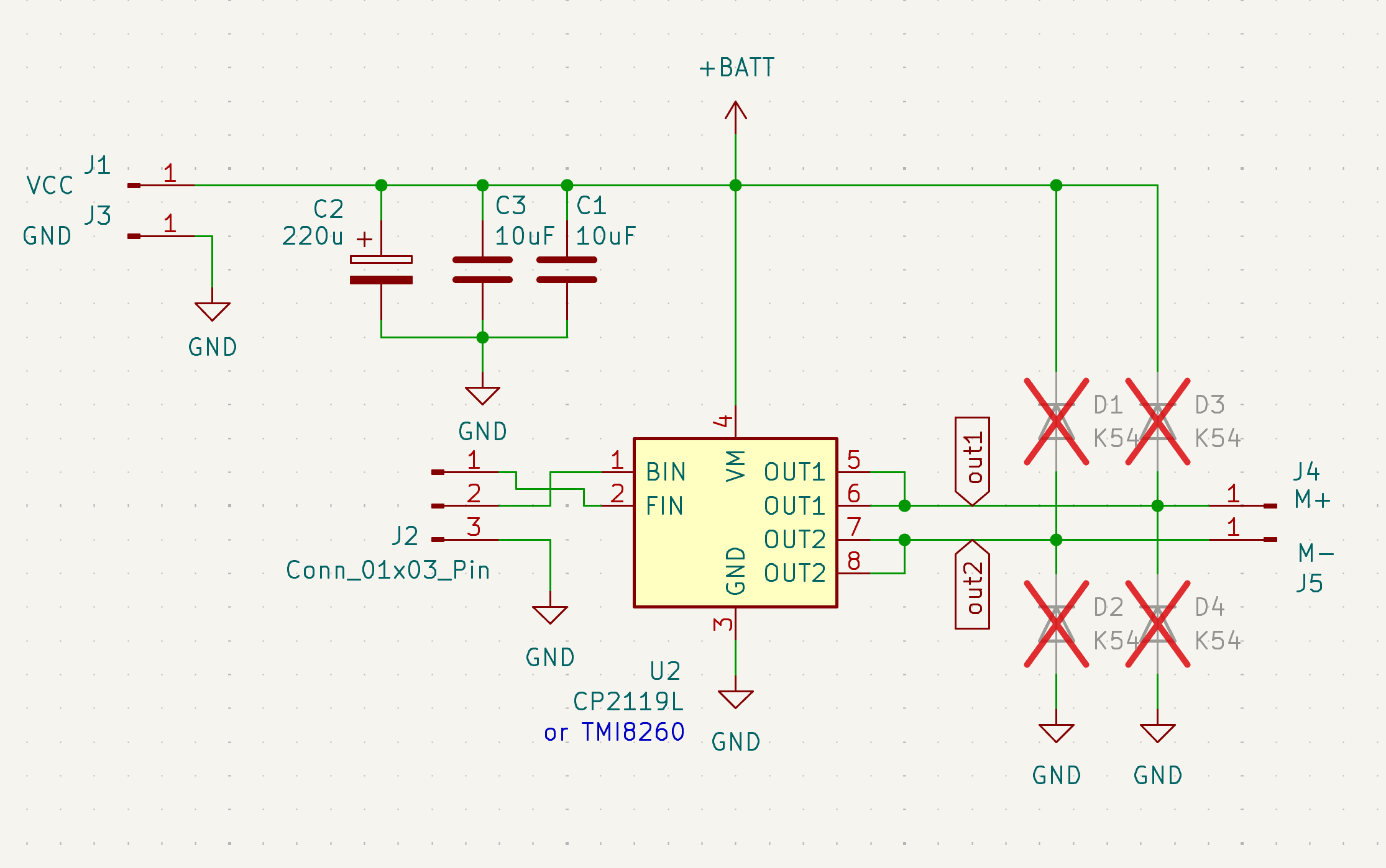
- Uses CP2119L or TMI8260SP integrated circuit
Basic operation
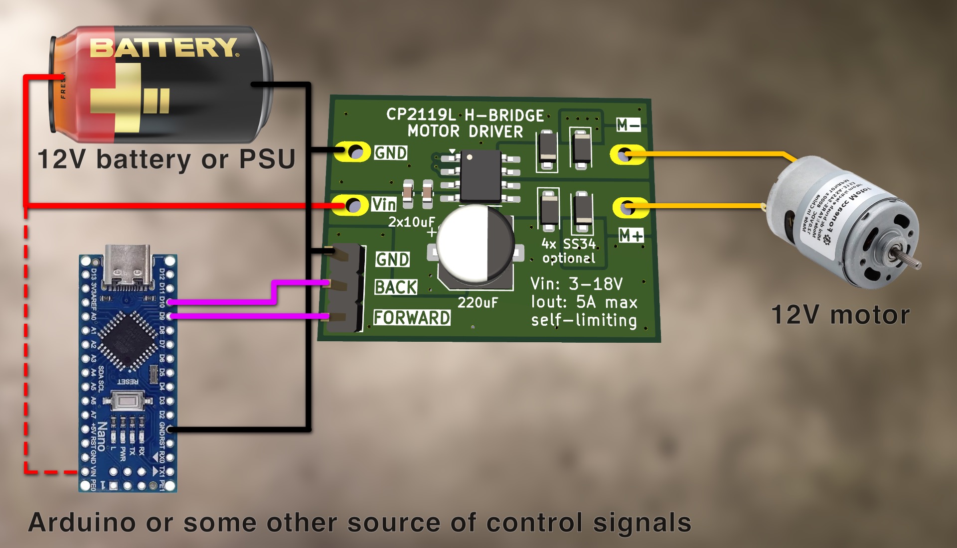
- Logic HIGH on the FORWARD pin makes the motor spin FORWARD (M+ becomes VIN, M- becomes GND)
- Logic HIGH on the REVERSE pin makes the motor spin REVERSE (M+ becomes GND, M- becomes VIN)
- Logic HIGH on BOTH pins makes the motor ACTIVELY BREAK (M+ becomes GND, M- becomes GND)
- Logic LOW on BOTH pins makes the motor FREESPIN (M+ floats, M- floats)
"Analog" control
- The power of the motor can be precisely adjusted (0-100%) by applying a PWM SQUARE WAVE to the FORWARD/REVERSE pins
- Recommended PWM frequency: 100Hz - 5KHz
- "analogWrite()" on Arduino produces a suitable 490Hz square wave with 255 levels of control
PCB assembly / component configurations
For Voltage 3-18V and Current 0-5A (basic configuration)
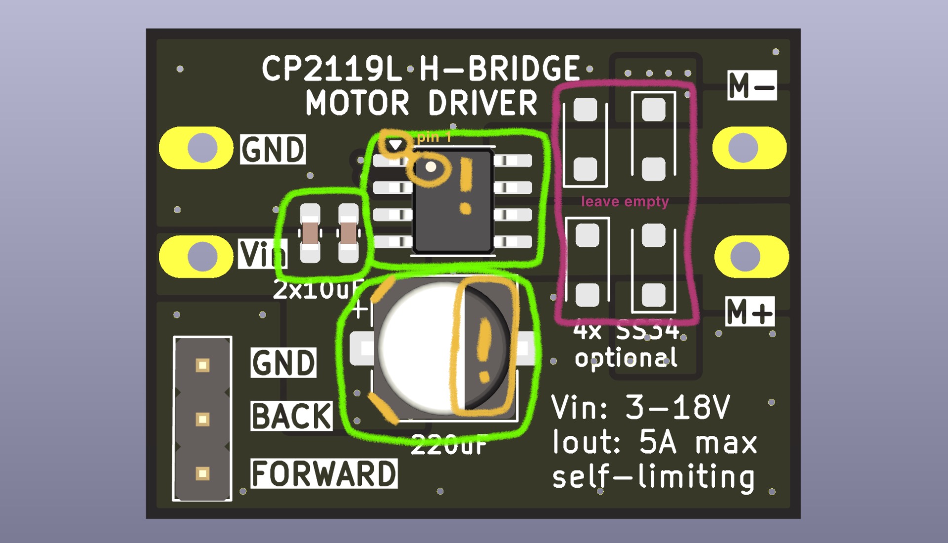
- Populate the TMI8260 (duh!). Note where pin 1 (marked) goes!
- Populate '2x10uF' with included ceramic capacitors
- Populate '220uF' with included polymer aluminium capacitor. Note where the negative goes!
- Skip the additional flyback diodes
- This works with PWM frequencies up to 5KHz
For PWM frequency > 5KHz
- If the expected current is low (<3A), you can probably just use the basic configuration
- Otherwise, add 4x flyback diodes on the PCB
- SS54 or SS34 diodes, in SOD-123L package
- They are difficult to solder, sorry!
For Voltage<10V AND Current<2A:
If you don't need the high power of this chip, consider using the DRV8835 module instead. It is cheaper and comes pre-assembled.
For ONE directional control:
If you don't need bi-directional control, consider just using a N-MOSFET and flyback diode instead. Cheaper, simpler.
Built in protections
The TMI8260/CP2119 has protection features that allow it to protect ITSELF
- It cannot protect the connected motor/coil - make sure VIN is a voltage that the motor can handle!
- It cannot fully protect the power source - make sure it can handle the current the motor will take!
Overcurrent / short-circuit protection
- If the connected motor / coil attempts to take more than > 9A, overcurrent protection kicks in
- The device will stop supplying power for approx 50 microseconds, and let the current drop
- After that, the device will automatically retry applying current
- This is very helpful when starting large motors from a standstill - the surge current will be effectively limited, and the motor will slowly spin up instead of taking infinity amperes.
- This does protect the power source by limiting the consumed current to approx 9A
- This feature relies on the inductance of the connected motor/coil. If the inductance is too low, the safety feature will not have time to react before the current becomes too high.
Overtemperature protection
- If the TMI8260 gets too hot (>150C) during continuous operation, it will temporarily stop providing power to the load
- After cooling down, it will automatically return to normal operation
Integrated flyback diodes
- Inductive loads tend to induct reverse voltages that may damage drive circuitry
- The TMI8260 has integrated flyback diodes (inside the chip) that can handle most use cases
- The PCB has space for additional external flyback diodes, for more extreme cases (see "Use cases")
Parts included in the kit:
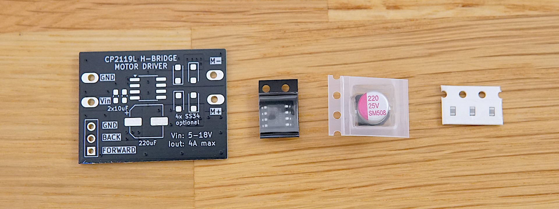
- Breakout PCB
- TMI8260SP-MS chip
- Polymer aluminium capacitor (SHENGYANG SM227M025E0600 220uF 25V)
- 3x Ceramic capacitors (10uF 25V 0603)
Documentation
 TMI8260SP-MS datasheet (in Chinese)
Future improvements
Thermal management
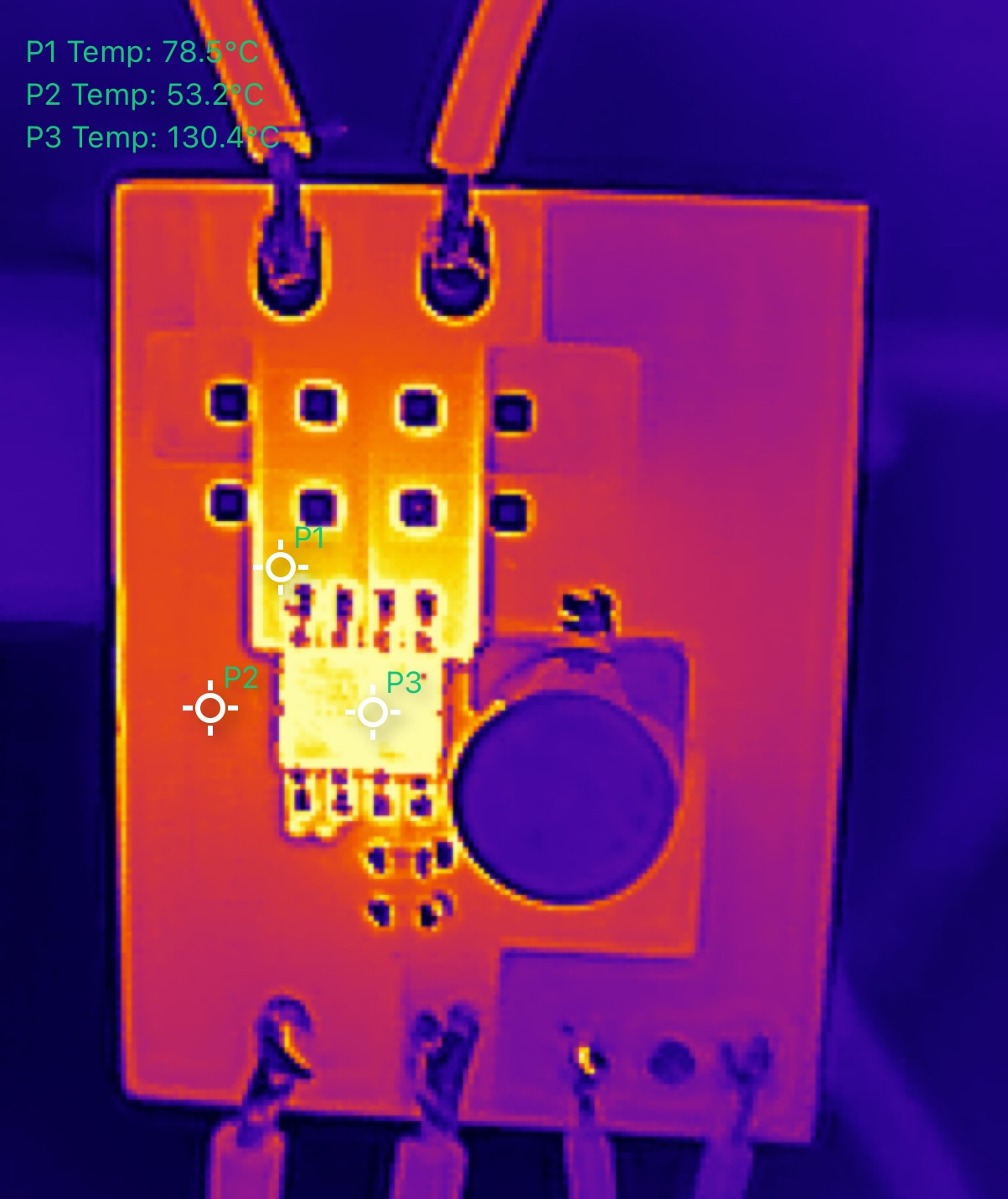
- Most of the heat from the IC seems to be dissipating though the OUT1 / OUT2 pins
- Therefore, the OUT1 / OUT2 polygons should be enlarged, for better cooling
- Maybe the IC should be moved more towards the middle of the board
- Right now the board can barely handle 5A
Solderability
- The large cap is very difficult to solder
- Some thermal reliefs can make it much easier, while probably not impacting performance in any significant way
- The optional flyback diodes are difficult to solder
- The footprint should be made hand-solderable (by enlarging the pad by a lot)
Made at ELAB by Marek Baczynski. Find him on the ELAB slack if you have any questions